
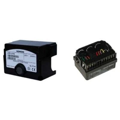
Siemens LFS1 Series Flame Safeguard Units
Product Description
Siemens Burner Controllers LFS Series (LFS1 Flame Safeguard)
Siemens LFS1 Series comprises microprocessor-based flame safeguard units for the supervision of industrial oil and gas burner flames. The devices evaluate flame detector signals and provide flame status information to compatible burner control systems.
Unlike a complete burner sequence controller, the LFS1 primarily performs flame supervision. It can be integrated with compatible Siemens burner controls, including LEC1, LME39.xxxRP and LME76 applications, or with appropriately engineered programmable logic controller (PLC) systems.
Key Features
- Flame Supervision: Monitors industrial oil and gas burner flames using specified detectors.
- Continuous Operation: Supported with RAR9 photocell detectors on LFS1.11 or ionization probes on LFS1.21.
- Intermittent Operation: Supported with compatible QRA UV detectors on LFS1.21; a controlled shutdown is required at least every 24 hours.
- LED Diagnostics: Multicolor indication of operating and flame status.
- Flame Signal Output: DC 0–10 V output for flame-strength indication only.
- BC Interface: Parameter setting and diagnostics using compatible Siemens accessories.
- Safety Functions: Undervoltage detection and potential-free NO / NC flame relay contacts.
- Multiple-Flame Applications: Suitable for separately supervising individual flames in appropriately designed systems.
Available Siemens LFS1 Models
- LFS1.11A1: AC 120 V, RAR9 photocell detector, oil flame supervision.
- LFS1.11A2: AC 230 V, RAR9 photocell detector, oil flame supervision.
- LFS1.21A1: AC 120 V, ionization probe or compatible QRA UV detector, according to operating mode.
- LFS1.21A2: AC 230 V, ionization probe or compatible QRA UV detector, according to operating mode.
Compatible Flame Detectors
- LFS1.11: Siemens RAR9 photocell detector.
- LFS1.21: Ionization probe, QRA2 / QRA2M, QRA4 / QRA4M and QRA10 / QRA10M.
- Important: QRA2M and QRA10M require the specified AGK30 auxiliary module. Verify the exact detector variant and wiring.
Industrial Applications
- Industrial oil and gas burners
- Industrial steam boilers and heating systems
- Combustion plants with central burner control
- PLC-based flame supervision systems
- Dual-flame and multiflame supervision installations
- Compatible industrial and marine burner applications
Safety and System Integration
The LFS1 supports safety-related applications up to SIL3 only under the conditions specified in the applicable Siemens Safety Manual T7782 and associated certification. The actual safety integrity capability must be assessed for the complete detector, safeguard and control configuration.
The DC 0–10 V output is intended for flame signal indication, not as a safety shutdown output. Safety-related flame status must be handled using the specified relay contacts and approved system architecture.
Product Selection Guidelines
Check the complete LFS1 model number, AC supply voltage, flame detector type, continuous or intermittent operating mode, relay contact requirements, compatible controller, BC interface accessories and applicable safety requirements.
Important: Installation, parameterization, safety verification and commissioning must be performed by qualified personnel in accordance with Siemens technical documentation.
Specifications
Siemens LFS1 Series Technical Specifications
| Brand | Siemens |
|---|---|
| Series | LFS1 Series |
| Product Type | Flame Safeguard / Flame Supervision Unit |
| Available Models | LFS1.11A1 / LFS1.11A2 / LFS1.21A1 / LFS1.21A2 |
| Fuel Applications | Oil / Gas, depending on model and detector |
| Rated Supply Voltage | AC 120 V (A1 models); AC 230 V (A2 models) |
| Mains Frequency | 50–60 Hz |
| Internal Power Consumption | 5 VA |
| Compatible Flame Detectors | LFS1.11: RAR9 Photocell Detector LFS1.21: Ionization Probe / QRA2 / QRA2M / QRA4 / QRA4M / QRA10 / QRA10M |
| Operating Modes | Continuous: RAR9 or Ionization Probe Intermittent: QRA UV Flame Detectors |
| Waiting Time (tw) | Max. 5 s |
| Flame-on Response Time (tan) | Min. 0.3 s at factory settings |
| Flame-out Response Time (tab) | Max. 1 s at factory settings |
| Time Parameter Adjustment | Parameters 217.00 / 217.01; increment 0.147 s, within specified limits |
| Flame Signal Output | DC 0–10 V (indication only; not safety-rated output) |
| Communication Interface | BC Interface |
| Output Contacts | Potential-free NO / NC flame relay contacts |
| Undervoltage Detection | Integrated |
| Degree of Protection | IP40 when correctly mounted |
| Operating Temperature | -20 to +60 °C |
| Relative Humidity | <95% RH |
| Installation Altitude | Max. 2,000 m above sea level |
| Compatible Plug-in Base | AGK11.7, ordered separately |
| Diagnostic Accessories | AZL2 / ACS410 / OCI410 with compatible interface accessories |
| Applicable Standards | DIN EN 298 / DIN EN 13611 / DIN EN 60730-2-5 |
| Safety Integrity Level | Up to SIL3 in certified configurations under Siemens Safety Manual T7782; detector-specific restrictions apply |
| Designed Lifecycle | 250,000 burner startup cycles; up to 1,000,000 cycles in specified industrial applications with switching loads ≤0.1 A |
| Reference Document | Siemens CC1N7782en (20.01.2026) |
Model Comparison
| Model | Supply Voltage | Fuel / Application | Flame Detector | Operating Mode |
|---|---|---|---|---|
| LFS1.11A1 | AC 120 V | Oil | RAR9 | Continuous |
| LFS1.11A2 | AC 230 V | Oil | RAR9 | Continuous |
| LFS1.21A1 | AC 120 V | Gas / Oil | Ionization / QRA UV | Continuous with ionization; intermittent with UV |
| LFS1.21A2 | AC 230 V | Gas / Oil | Ionization / QRA UV | Continuous with ionization; intermittent with UV |
Technical Note: Response-time values are based on factory settings. Parameter changes must comply with Siemens limits and tolerances. QRA UV supervision requires controlled shutdown at least every 24 hours. The DC 0–10 V output is intended for indication only. Verify SIL capability using the applicable detector, safety manual and complete system design.
Product Specifications
Siemens LFS1 Series Technical Specifications
| Brand | Siemens |
|---|---|
| Series | LFS1 Series |
| Product Type | Flame Safeguard / Flame Supervision Unit |
| Available Models | LFS1.11A1 / LFS1.11A2 / LFS1.21A1 / LFS1.21A2 |
| Fuel Applications | Oil / Gas, depending on model and detector |
| Rated Supply Voltage | AC 120 V (A1 models); AC 230 V (A2 models) |
| Mains Frequency | 50–60 Hz |
| Internal Power Consumption | 5 VA |
| Compatible Flame Detectors | LFS1.11: RAR9 Photocell Detector LFS1.21: Ionization Probe / QRA2 / QRA2M / QRA4 / QRA4M / QRA10 / QRA10M |
| Operating Modes | Continuous: RAR9 or Ionization Probe Intermittent: QRA UV Flame Detectors |
| Waiting Time (tw) | Max. 5 s |
| Flame-on Response Time (tan) | Min. 0.3 s at factory settings |
| Flame-out Response Time (tab) | Max. 1 s at factory settings |
| Time Parameter Adjustment | Parameters 217.00 / 217.01; increment 0.147 s, within specified limits |
| Flame Signal Output | DC 0–10 V (indication only; not safety-rated output) |
| Communication Interface | BC Interface |
| Output Contacts | Potential-free NO / NC flame relay contacts |
| Undervoltage Detection | Integrated |
| Degree of Protection | IP40 when correctly mounted |
| Operating Temperature | -20 to +60 °C |
| Relative Humidity | <95% RH |
| Installation Altitude | Max. 2,000 m above sea level |
| Compatible Plug-in Base | AGK11.7, ordered separately |
| Diagnostic Accessories | AZL2 / ACS410 / OCI410 with compatible interface accessories |
| Applicable Standards | DIN EN 298 / DIN EN 13611 / DIN EN 60730-2-5 |
| Safety Integrity Level | Up to SIL3 in certified configurations under Siemens Safety Manual T7782; detector-specific restrictions apply |
| Designed Lifecycle | 250,000 burner startup cycles; up to 1,000,000 cycles in specified industrial applications with switching loads ≤0.1 A |
| Reference Document | Siemens CC1N7782en (20.01.2026) |
Model Comparison
| Model | Supply Voltage | Fuel / Application | Flame Detector | Operating Mode |
|---|---|---|---|---|
| LFS1.11A1 | AC 120 V | Oil | RAR9 | Continuous |
| LFS1.11A2 | AC 230 V | Oil | RAR9 | Continuous |
| LFS1.21A1 | AC 120 V | Gas / Oil | Ionization / QRA UV | Continuous with ionization; intermittent with UV |
| LFS1.21A2 | AC 230 V | Gas / Oil | Ionization / QRA UV | Continuous with ionization; intermittent with UV |
Technical Note: Response-time values are based on factory settings. Parameter changes must comply with Siemens limits and tolerances. QRA UV supervision requires controlled shutdown at least every 24 hours. The DC 0–10 V output is intended for indication only. Verify SIL capability using the applicable detector, safety manual and complete system design.
Company Information
บริษัท บุญเยี่ยมและสหาย จำกัด
Visit Supplier Profile